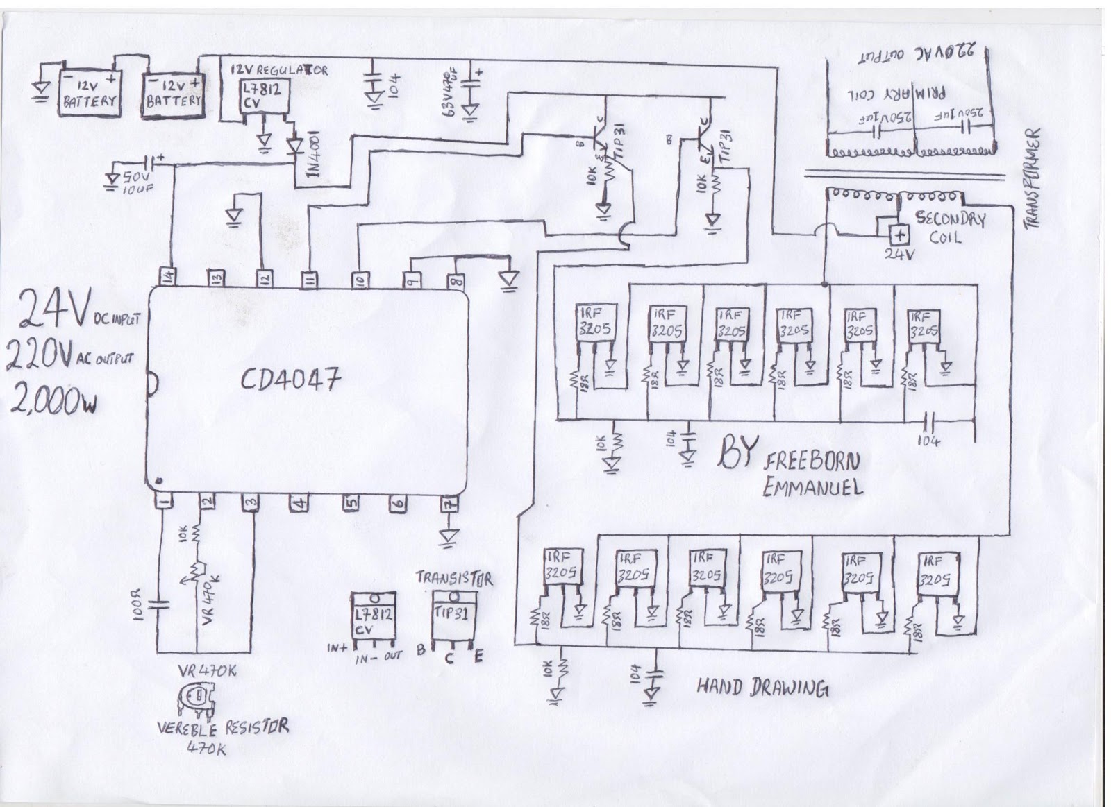
Split Phase Inverter Schematic [diagram] 50 Rv Wiring Diagra
Sine wave inverter circuit diagram with full explanation Induction capacitor connect 2020cadillac electricala2z dol Fig.6 split phase motor wiring diagram
High Frequency Inverters with Split Phase Capability and High Surge
Motor phase diagram wiring single split induction electric motors capacitor run connection types fig leads explained schematic electrical internal find 3 phase inverter wiring diagram 12kw hybrid split phase inverter 10kw split phase solar inverter off
120/240v split phase inverter
Inverter circuit wave sine sg3525 using modified 3525 ic protection low circuits output diagram power battery projects board control wattSplit phase inverter schematic Three-level single phase inverter circuitInverter split phase output bridge full schematic misunderstood meant perhaps been has.
Inverter split systemInverter circuitry scheme schematics battery Split phase inverter schematic of ac and inverter mode[diagram] 50 rv wiring diagram split phase inverter.

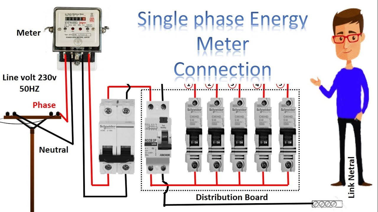
Energy meter circuit diagram ppt
Split phase inverter schematicSplit phase output from full bridge inverter Modified sine wave inverter circuit using ic 3525, with regulatedSplit phase wiring diagram.
Single phase full bridge inverterInverter circuit wave sine diagram board schematic power solar arduino full electronics projects inverters 1000w using diy 1kw charger ic [diagram] 50 rv wiring diagram split phase inverterSingle phase pwm inverter.

High frequency inverters with split phase capability and high surge
Inverter circuit 500w, 12v to 220vInverter conduction wiring schematics circuitdigest sine Inverter mosfet arduino circuits diagramsInverter aims rv.
Educatore genuino elettronico inverter h bridge mosfet circuit perizomaInverter ac circuit diagram Inverter 220v how2electronics12v dc to 220v ac inverter circuit & pcb.

Circuit inverter 100w simple diagram
Split phase inverter [50-amp rv service]What is a split phase induction motor? Schematic diagram of single phase full-bridge inverter circuit6 best – simple inverter circuit diagrams – diy electronics projects.
Inverter 500w 220v 220vac 24vdc 300w 24v elettrico volt circuits eleccircuit transformer pcb schematics daya invertor rangkaian modifying watt mosfet3 phase to single phase wiring diagram Igbt inverter circuit diagram wiring view and schematics diagramSimple 100w inverter circuit.
Power circuit diagram of an igbt based single phase full-bridge
Split phase inverter schematicPhase induction windings winding circuit applications stator principle auxiliary motors resistor circuitglobe What is split phase?.
.


